Current Collaborators: A. I. Akinwande (EECS), K. Cheung (Ph.D. EECS’09)
Funding: DARPA/MTO
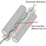
A quadrupole is a device composed of four electrodes arranged in a symmetric manner that can filter charged species if driven with a mix of constant and time-varying electric potentials. The dynamics of a charged particle inside a quadrupole mass filter (QMF) are described by the Mathieu equation. The Mathieu equation defines an infinite number of stability regions, i.e., combinations of DC voltage, RF amplitude, RF frequency, and electrode separation that result in stable (confined) trajectories of particles with a certain specific charge (Fig. 1). Most of the work reported on QMFs has focused in the first stability region, but we have pioneered the use of the second stability region for MEMS QMFs.
QMFs are arguably the most popular mass filters due to their simple design and operation. The development of scaled-down QMFs has stirred noticeable interest for over a decade. The motivation behind this effort is driven by the desire for rugged mass spectrometry (MS) systems that are smaller, lighter, cheaper, faster, and more power efficient. The successful implementation of portable MS would significantly impact areas such as law enforcement, geological analysis, environmental monitoring, and space exploration.
Besides the obvious reduction in weight and volume, scaled-down QMFs are ideal for portable MS systems because they can operate at higher background pressures. The largest dimension of a QMF should be smaller than the mean free-path of the background gas to avoid interference with the filtering dynamics of the QMF. The relaxation of the vacuum level at which the QMF can operate results is less power consumption by the pump system of the MS.
Despite these potential advantages, miniaturization of QMFs results in reduced transmission, demanding good assembly precision, and increased drive-circuit complexity (the scaled-down QMFs require higher RF drive frequencies for operate with good resolution, and the decrease in their capacitance should lead to dominating parasitics). However, the loss of transmission can be recovered by operating at higher pressures and/or the use of quadrupole arrays.
We have developed two distinctive MEMS QMF technologies: the mGripper and the MuSE. Both technologies have demonstrated performance on par with the state-of-the-art QMFs.
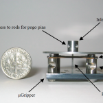
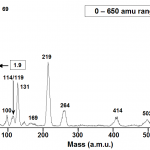
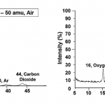
The mGripper: One of the MEMS QMF technologies that we have developed relies on silicon DRIE-patterned deflection springs to aid the precision hand-assembly of out-of-plane devices. The mGripper technology has allowed us to implement quadrupoles with electrode radii down to 250 mm and arbitrary electrode aspect-ratio (Fig. 2). Using The mGripper technology, we have implemented QMFs that are able to span a mass range up to 650 amu (Fig. 3). One of the most important contributions of our work in MEMS QMFs is demonstrating that operation of scaled-down devices in the second stability
region results in visibly better resolution and smoother peaks (Fig. 4). In more detail, the operation of the QMF in the second stability region decreases the handicaps from larger relative misalignment in the QMF compared with the macro versions, which opens the doors to high-performance portable analytical instrumentation. With this technology we have been able to obtain resolutions as large as 125.
The MuSE: The other MEMS QMF technology that we have developed comes from rethinking the way MEMS QMFs are made and, in our opinion, it represents a new paradigm for batch-fabricated QMFs. Until then, all MEMS QMFs (including the mGripper) involved batch-fabricating using microfabrication techniques the housing for the electrodes, to then serially assemble each quadrupole. A closer look at the problem reveals that there is an alternative to this trend. Originally, QMFs have hyperbolic electrodes that define a pure quadrupole electric potential between the electrodes. However, hyperbolic electrodes are expensive to manufacture. Therefore, a quadrupole with circular electrodes was proposed with an optimized electrode spatial distribution that emulates as close as possible the quadrupole field by minimizing the other harmonics. Circular rods are far easier and cheaper to make with tight tolerances, and even though QMFs with circular rods have less resolution that QMFs with hyperbolic
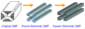
electrodes, the trade-off is favorable so most commercial QMFs use circular rods. The perturbations in the electric potential introduced by the new electrode shape are small because electrostatics is a boundary value problem, i.e., the solution of the electric potential far from the constant-potential boundary is not strongly influenced by the features of such boundary –this is the reason why software like SIMION that discretize a region with smooth boundary into a collection of regions defined by a Cartesian mesh can accurately simulate electrostatics. The perturbations in the electric potential are smaller the farther the point is from the boundary, which is the region where most of the ions are transmitted (the region next to the axis). QMFs need high-aspect-ratio electrodes to have good resolution, and circular high-aspect-ratio structures are very hard to make using batch microfabrication techniques. Using DRIE it is straight forward to etch trenches with straight sidewalls. Therefore, a QMF that uses rectangular electrodes can be batch-micro fabricated. Optimization of the geometry to eliminate the undesired harmonics results in square electrodes with electrode separation equal to the electrode width -MuSE comes from “micro square electrode” (Fig.5).
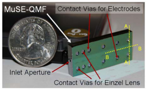
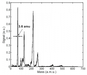
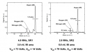
We have implemented fully batch-fabricated MEMS QMFs using the MuSE technology (Fig. 6). The device is a 5-wafer stack that is made with DRIE and fusion wafer bonding. The MuSE technology can readily implement monolithic integrated ion optics and pre-filters to the QMF. These devices are also able to span a mass range up to 650 amu (Fig. 7). However, one or the drawbacks of the technology is that about 30% more bias voltage is required to resolve the same mass compared to a QMF with circular rods. Also, the typical peak shape of these QMFs operated in the first stability region has some characteristic precursors in the low-mass side of the peak. However, the MuSE technology can also adopt the paradigm of operation in the second stability region to achieve visibly better resolution and smoother peaks (Fig. 8). Therefore, we believe that the trade-off is favorable and that MuSE QMFs will ignite a revolution in portable MS systems. With the MuSE technology we have been able to obtain resolutions as large as 80.
