Current Collaborators: Professor A. I. Akinwande (EECS), B. Gassend (Ph.D.’07)
Funding: DARPA/MTO
Needles are widely used in a broad range of applications including drug delivery, field enhancement, and packaging (anchoring of devices). In all these applications, scaling-down of the needles is advantageous in ways that are intimately related to their function. For example, scaled-down needles for biological probing and drug delivery have a three-dimensional geometry designed to decrease the trauma to the skin and tissue due to penetration, while still providing enough stiffness to avoid structural failure of the needle during insertion. Also, scaled-down needles allow local probing of a tissue, and a massive array of needles would enable global monitoring of the biological system at length scales far larger than the needle dimensions. Similarly, scaled-down needles used as electrospray emitters are hundreds of microns tall, hundreds of microns apart, and have submicron tip radii so that they can interact with liquids and turn-on with low voltage. Finally, the needles used as electron field emitters have nanometer-sharp tips to achieve low-voltage operation.
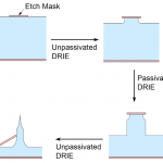
Model for Needle Design: We have concentrated our research on the development of silicon-based Deep Reactive Ion Etched (DRIE) needle-like solid structures, i.e., DRIE-patterned high aspect-ratio solid structures that have sidewalls with non-constant slope along their heights and that end in sharp protrusions. In particular, we have developed a model that is very helpful to design complex high aspect-ratio silicon needles. In this model, the needle-like structures are fabricated using a sequence of passivated (the standard DRIE process) and unpassivated (no fluorocarbon-based plasma in the process) DRIE steps that in combination with an etch mask achieves a certain geometry, including ultrasharp tips. The model does not simulate the dynamics of the interaction between the plasma and the substrate, or makes corrections for microloading, scalloping, etch window variation, or any other effect that could affect the etch uniformity. Each etching step is described by the etch depth and etch profile:
-
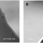
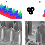
Fig. 2. A sharp silicon tip formed when three etch fronts meet (A), and a blade-like tip formed when four etch fronts mee Each unpassivated DRIE step is modeled as an etch process with an etch rate that is a function only of the normal of the surface being etched. If this function is uniform, the resulting etch is isotropic. However, the bias power of the unpassivated DRIE step produces some anisotropy, making the vertical etch rate higher than horizontal etch rate.
- or the passivated DRIE steps, the etch proceeds vertically at a uniform rate, except in areas directly below the etch mask, which are assumed unetched by the plasma. This model for the passivated DRIE implies that the bottom of a partially etched wafer remains flat across the full extent of the etch surface.
The resulting shape after a passivated or unpassivated DRIE step is complete can be represented by two 2D functions that vary along the surface of the wafer. In both cases, a first function z(x,y) defines the depth of the silicon etch at the beginning of the step at each (x,y) location, where x, and y are Cartesian coordinates on the wafer surface using a coordinate system with axes in the <100> direction (for example, the x- and y- axis can be respectively parallel and perpendicular to the wafer flat in a <100> wafer). For passivated DRIE steps, a second function M(x,y) defines the areas of the wafer that are protected by an etch mask. The function M(x,y) only takes on the values 1 or 0 indicating the presence or absence of masking material, respectively. A passivated DRIE step does not produce undercut, i.e., the etch mask acts as an umbrella that protects the silicon directly below it, even if it is not in direct contact to the etch mask. Therefore, after a passivated DRIE step of depth d, the function z becomes z’
z′ = z (x,y) + d · M (x,y)
(1)
For unpassivated DRIE steps, a concave shape function is used instead as second function. S can take on real values or −∞, and for normalization purposes . In general, the shape function S is smooth wherever it is finite. After an unpassivated DRIE step of depth d, the function z becomes z’
(2)
The maximization considers all the positions where the silicon is exposed (i.e., it includes silicon not directly in contact with the etch mask) to determine how deep the etch has progressed at a given (x,y) point. In effect, the shape function S defines the cavity that a hard mask with a point-hole in it creates during an unpassivated DRIE step, once the silicon directly below the hole has receded by a unit distance. The model of the unpassivated DRIE step states that the etching proceeds from the exposed silicon surface in all directions, with an etchrate that is a function of the tilt of the sidewall by the shape function S. From fabrication results we concluded that S defines a roughly ellipsoidal shape with a vertical z-axis length twice the length of any of the in-plane x and y axes. Also, the model can take into account a slight lattice orientation-dependent anisotropy in the silicon etch that was experimentally observed. Specifically, the fabrication results suggest that unpassivated DRIE steps have a small dependence in crystal plane orientation that causes a slight bulge in the x and y axes of an ellipsoidal etch, compared to the x and y axes rotated by 45° with respect to <100> (see Section III). In the model, the shape function S for unpassivated DRIE steps carried out on a <100> wafer is
(3)
where β is a parameter that describes the directionality of the etch, and a is a parameter that characterizes the lattice orientation-dependent anisotropy. When the result of Eq. 3 is not a real number, it is set to S(x, y) = −∞. The constant β was empirically found to vary across the wafer with a typical value around 2. Taking from now on β=2, empirical results lead to values of α of about 18.5. For α = 0, Eq. 3 results in an ellipsoid with a z-axis of length = 1, and x- and y-axis of length of 1/β, i.e., 0.5. The x2y2 term in Eq. 3 is the lowest-order correction of the symmetry of the etch shape. This correction was sufficient to explain the small anisotropies that were found in the experimental results on <100> Si wafers.
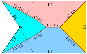
Ridge Formation and Ultrasharp Tips: It is possible to create ridges in an otherwise smooth surface of needle-like structures etched with a single unpassivated DRIE step. These discontinuities are predicted by the model. According to the model, the ridges occur when control of the etch depth jumps discontinuously from one point to another on the edge of the mask, i.e., where two or more etching fronts meet. As illustrated in Fig. 1, the etch depth of most points below the mask is set by a single point on the edge of the mask. In the figure, each colored region corresponds to points whose depth is set by a given concave stretch of the mask boundary (a stretch in which the border only turns away from the inside of the mask). In each region, the maximum in Eq. 2 is reached at exactly one point on the corresponding concave stretch of the boundary. When two regions meet, the maximum is attained in more than one way. In this case, moving slightly away from the boundary causes different mask edges to dominate. The regions dominated by two distant mask edges will not have the same surface normal; therefore, a normal discontinuity is present where these two regions intersect. Likewise, when three regions intersect, a tip is formed.
There are two ideas from computational geometry that are helpful to determine the location of the ridges. These relationships are only exact if α is zero, i.e., when S(x, y) has symmetry of revolution. However, the fabrication results demonstrate that the departure from symmetry of revolution in the unpassivated DRIE steps is small enough that it does not have a significant impact on the final shape of the structure. The two ideas are the Medial Axis Transform (MAT) and the distance transform. Specifically:
- The MAT of a region is the set of points for which there is more than one closest point on the boundary of the region. For a polygon, the MAT is made up of portions of angular bisectors of edges, perpendicular bisectors of vertices, and parabolas that have one edge as a directrix and one vertex as a focus. The MAT of the etch mask defines the projection of the ridges on the etch mask surface. The MAT can easily be sketched by hand and is an excellent aid in designing mask shapes for microneedles.
- The distance transform of a mask shape is a function DT(x,y) that maps each point in the plane to the distance from that point to the closest point outside the mask. This function is zero in areas not covered by the mask, and steadily increases inside the mask. Eq. 2 is closely related to the definition of the distance transform, so that the final shape of the needle-like structure can be expressed by
(4)
where f is a function that depends on the sequence of etches that was performed. The ridges arise because DT(x, y) is not smooth on the MAT.
So far, only needle-like structures formed from a single unpassivated DRIE step have been discussed. Another type of ridge appears when a passivated DRIE step is part of the sequence because the passivated DRIE steps introduce discontinuities in f. These discontinuities lead to discontinuities in z(x,y), with an edge at the top of the corresponding vertical DRIE sidewalls.
Fabrication results show that DRIE-patterned sharp tips can only be reliably obtained if the tip is formed at the meeting point of only three ridges (Fig. 2 A). If one of the ridges is shifted because the etch is progressing at a different rate compared to the other two ridges, the position of the tip is moved slightly, but the tip remains sharp. This is unlike the case where four or more ridges are involved in the formation of the tip, in which the tip can become a straight edge (Fig. 2 B). Moreover, the three ridges should ideally meet at 120° from each other so that the tip is symmetric.
Model Comparison with Fabricated Structures: This section provides only a qualitative evaluation of the model, that is, an evaluation of the visual resemblance of the etched structures to the predictions of the model. Because of the large radial non-uniformity typically attained with DRIE, a quantitative comparison would require the use of etch depths and shape functions that depend on the position on the wafer. All experimental results in this section come from <100> silicon wafers.
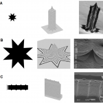
Basic Needles: Figure 4 shows various scaled-down needles fabricated using the base process flow shown in Fig. 3. There is good agreement between the model predictions and the fabrication results. The needles shown in Fig. 4 are 300 to 400 µm tall. The pencil-like needle (Fig. 4 A) was fabricated using an 8 point star with 100 µm ID and 200 µm OD as etch mask, and it required 50 µm of underetching before its etch mask detached, as well as 300 µm of passivated DRIE etching . The conical needle (Fig. 4 B) uses the same mask shape as the pencil-like needle, scaled-up four times (etch mask is an 8 point star with 400 µm ID and 800 µm OD). This type of needle requires 200 µm of underetching and no passivated DRIE etching at all. The mask for the needle with a serrated top edge (Fig. 4 C) is a rectangle 130 µm wide with periodic triangular outcroppings (teeth) separated 100 µm along the direction of the ridge. The tooth angle is 45 ̊, i.e., there is a right angle of the mask at the end of each tooth. This type of needle requires 50 µm of underetching. The model correctly predicts the position of the tips in Fig. 4 C. However, the graphical results of the model show the tips rising above the rest of the needle edge more than in the SEMs, and they also miss the slight curvature of the ridge between adjacent tips. The disagreement between the tip height predicted by the model and the experimental result might be due to slight over-etching of the sample. Moreover, the model does not account for a partial shadowing effect caused by the mask that is stronger the closer to the points of contact between the mask and the substrate (i.e., the tips). This effect is similar to microloading, but inherently related to etches with isotropy. The partial shadowing will cause progressively more material to be removed farther from the tips, and hence the curvature that is observed in the SEM. The model is unable to capture this effect as it only considers shadowing from the nearest mask-edge to any given point. Thus, the model incorrectly predicts that the ridge should be flat more than one mask-tooth half-length away from the tip.
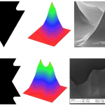
Complex Needles: The results shown in fig. 5 were obtained using three unpassivated DRIE steps interleaved with two passivated DRIE steps. In general, there is good agreement between the model and the fabrication results. The fabrication results are similar to the fabrication results obtained by other researchers with grayscale lithography and passivated DRIE; however, the slope transitions in our results are smoother. In Fig. 5.A the full width of the mask is 340 µm, while in Fig. 15.B the whole shape is inscribed in a circle of radius 400 µm. The most striking discrepancy between the model and the fabricated result is in Fig. 5.A, where the sharp vertical ridges predicted at the tips of the star-like structure were largely eroded away in the sample, to the point where the SEM shows a convex ridge-line where the model predicted a concave ridge-line with a sharp corner. This discrepancy is most likely due to the sharpness of the star’s points. First, any small amount of over-etching will significantly move the ridge-line. Second, the sharp corner predicted by the model is likely to enhance the local electric field, which will lead to an increase of ion bombardment and excessive etching. Finally, the sample shown in Fig. 5.A was slightly over-etched compared to the model, reducing how much the central part of the tip extends above the star shape. The structure shown in Fig. 5 B has capillary-like features in an attempt to increase the flowrate that could be delivered by the structure if used electrospray applications (externally-fed emitter).
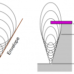
Tapered DRIE: The model we developed can also be used to predict tapered DRIE. If the passivated and unpassivated DRIE steps are alternated in short sequences, the resulting sidewall is the envelope of a set of ellipsoids, which is an inclined straight line (Fig. 6).
In principle, any taper could be obtained with this method by varying the proportion of the total etch made by all the unpassivated and passivated DRIE steps compared to the total etch depth. As expected, a constant taper is obtained only if short unpassivated and passivated DRIE steps are alternated. The top of the etch profile is set by the largest ellipsoid, which results in having a chamfer on the sidewall next to the etch mask. Because of this chamfer, there is a practical limit to how far from vertical the tapered sidewall can be. As the sidewall becomes shallower and shallower, the “top edge effect” becomes the dominant part of the structure, limiting practical sidewall angles to at most 30 to 45 degrees from vertical. The bottom of the etch profile is defined by the smallest ellipsoid, which in principle can be set arbitrarily small. Tapered sidewalls can also be implemented without the need of a series of passivated and unpassivated DRIE steps by implementing a series of short etching and polymer coating steps so that the sidewall passivation runs out before the end of the etch step, which results in non-vertical taper. Using this reasoning, we modified one of our standard DRIE recipes to fabricate needles with 70° sidewalls (Fig. 7).
We have available for download a .zip filed with two implementations of the model and an example. One implementation of the model is written in C+, while the other implementation is a Matlab script. The inputs of the model are the etch mask and the sequence of passivated and unpassivated DRIE steps, including the etch depths of each step. The final shape is an alternation of straight vertical sidewalls and curved inclined surfaces. The straight vertical sidewalls are generated during the passivated DRIE steps, and etched inward by subsequent unpassivated DRIE steps. Each unpassivated DRIE step generates a curved inclined surface. The surface for a given unpassivated DRIE step is generated by moving a scaled shape function S across all points in the silicon surface that are reachable by the plasma at the beginning of the step. Depending on the etch sequence, the surfaces generated during some etch steps will disappear completely as neighboring surfaces expand and consume them. This is the link to download the file:
