
Current Collaborators: Frances A. Hill, Eric V. Heubel (MechE)
Former Collaborators: A. I. Akinwande (EECS), M. Martinez-Sanchez (Aero/Astro)
Funding: DARPA/MTO, AFOSR
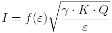
In one of the ESI emitter architectures that we are exploring, the working liquid is fed into the emitter in such a way that the exterior of the emitter is kept dry. These emitters are similar to capillaries. Our emitters use liquids with large electrical conductivities (larger than 1mSi/m) while working in the steady-state single-Taylor cone droplet regime, where beam divergence is small and droplet size distribution is close to monochromatic. To first-order, in the steady-state single-Taylor cone droplet regime the ESI emitter acts as a current source. The relationship between the emitted current I and the volumetric flowrate Q is
 (1)
(1)
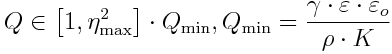
where K is the electrical conductivity of the liquid, e is the relative electrical permittivity of the liquid, and is a dimensionless function equal to about 20 for ε ~ 40. The flowrate of an ESI emitter operating in this regime falls into a rather wide range:
 (2)
(2)
where r is the density of the liquid, Qmin is the minimum flowrate (a property of the liquid), and hmax is the maximum dimensionless flowrate, which researchers have shown could be as high as 10. From eq. 2, it is clear that ESI emission has the highest specific charge (charge per unit of mass flowrate) when the flowrate is the lowest. One can show that the total current Iarray from an array of n ESI emitters working uniformly while jointly delivering a total volumetric flowrate Qarray is
 (3)
(3)
i.e., there is a net augmentation of in the emission current coming from an array of ESI emitters compared to a single emitter if the total flowrate is the same. Therefore, an array of ESI emitters allows both augmentation of the total flowrate output and maximization of the specific charge.
Another reason for making ESI emitters work near the minimum steady-state flowrate is to produce droplets as small as possible. In the single-Taylor cone droplet regime, the Taylor cone ejects from its apex a jet that breaks-up into droplets. The droplet diameter ÆD depends on the stability that breaks-up the jet. The break-up mechanism depends on the ratio of the electric normal stress over the surface tension stress. On the one hand, the jet could break into droplets because of a varicose instability (Rayleigh instability) if this stress ratio is small. In this case, the ÆD is approximately
 (4)
(4)
On the other hand, the jet could break-up because of a whipping instability, which occurs when the flowrate and current is large. In this case, the droplet diameter is approximately
 (5)
(5)
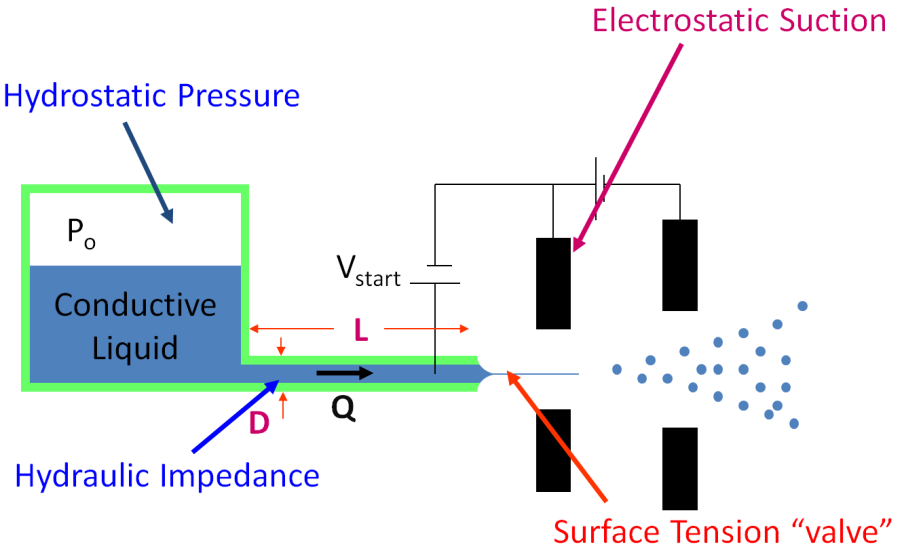
Flow Control: We have pioneered a strategy for electrical control of the electrospray emission without using moving parts. In this control scheme (Fig. 1), each emitter is backed up by a large hydraulic resistance. The pressure difference between the plenum and the exterior is such that would set a flowrate that falls within the range for steady-state single-Taylor cone droplet emission. However, flow does not occur because of the meniscus at the emitter tip. There is a maximum pressure difference that the meniscus can withstand before breaking up, with is larger than the pressure difference between the plenum and the exterior. The pressure difference between the maximum meniscus pressure and the plenum pressure is provided by electrostatic suction, i.e., by biasing a voltage between the emitter and the extractor. We have been successful at demonstrating this method of flow control, provided the emitter tip is non-wetting so the wetting front of the meniscus is well defined. The movie section of the webpage contains a video that documents the flow control we just described (click here to see the movie).
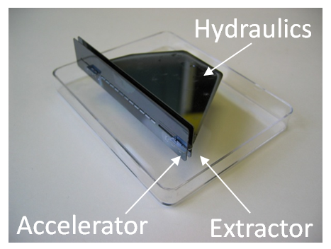
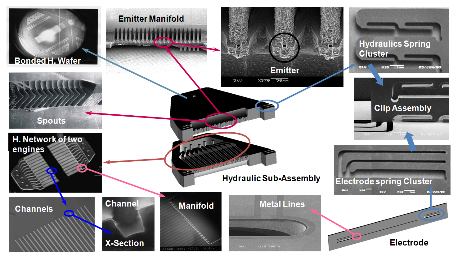
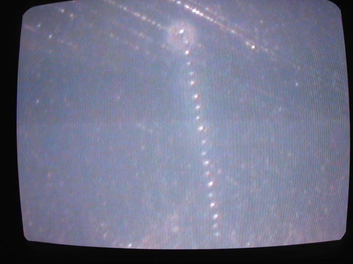
We have developed a linear array of internally-fed electrospray emitters composed of a two-wafer stack for the main body and two substrates for the electrodes (Fig. 2). The device was originally intended for space applications and it used formamide highly doped with ionic salts (Si/m-level electrical conductivity). However, the technology development is applicable to a wide range of liquids. The device is composed of a plenum that evolves into twelve manifolds, each manifold feeding 20 emitters (Fig. 3). The emitter pitch is 130 um (769 emitters per cm). The properties of the working liquid are such that it required very high-aspect-ratio (1500:1) channels to implement electrical flow control. Therefore, the channels were carved on a wafer surface, instead of through the wafer thickness. The electrodes of the array was assembled using clusters of DRIE-patterned springs, a high-voltage MEMS packaging technology that we pioneered and that we have developed for almost a decade. Fig. 4 shows the imprints of one of the manifolds, evidencing uniform emission.
The electrospray technology implemented in the linear array is quite efficient. Typical efficiencies are in the 70 – 80 % range, where majority of the losses are in the polydispersity of the plume, the viscous losses in the Taylor cone, and the energy spend generating the droplet surfaces (Fig. 5)