Current Collaborators: Frances Hill
Former Collaborators: A. I. Akinwande (EECS), M. Martinez-Sanchez (Aero/Astro), B. Gassend (Ph.D. EECS’07)Funding: DARPA/MTO, AFOSR
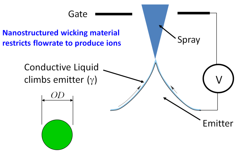
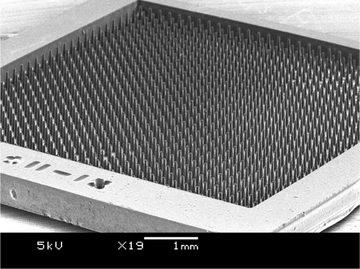
In the other of the ESI emitter architectures that we are exploring, the working liquid is fed into the emitter in such a way that the exterior of the emitter is kept wet. These emitters are either fully porous or their surface is covered by a nanostructured porous material (wicking material). The majority of our work has concentrated in solid emitters conformally coated with plasma-deposited/grown nanostructured wicking materials, particularly black silicon (Fig. 1). In this case the start-up voltage is given by
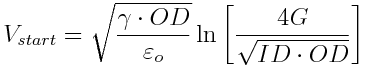 (1)
(1)
The externally-fed emitter architecture is advantageous if the working liquid has small vapor pressure (vacuum applications). The bulk of our work in multiplexed electrospray using externally fed emitters has used ionic liquids as working fluid. By using nanostructured porous materials we have been able to achieve very high hydraulic impedances to individually control each of the ESI emitters to achieve uniform operation in the ionic regime. In the ionic regime the spray is composed of solvated ions, which results in visibly larger specific charges than in the droplet regime, opening new applications for ESI technology. For example, a thruster with a plume composed of particles with large specific charge delivers thrust at a larger specific impulse, which is very attractive to save propellant mass (long-term missions). The flow control implemented in this architecture is analogous to the flow control used in the internally-fed ESI sources. However, since the fluid is not pressurized, the technology is safer to unwanted emission, flooding, and pills. In this kind of ESI emitter the electric field acts as a pump, with the surface tension effects helping filling-in the porous material.
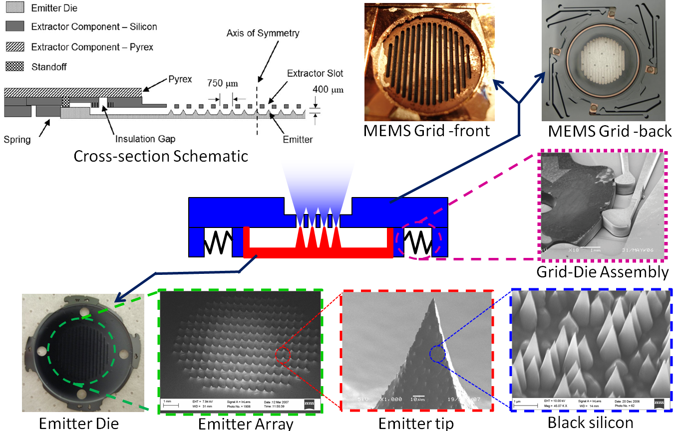
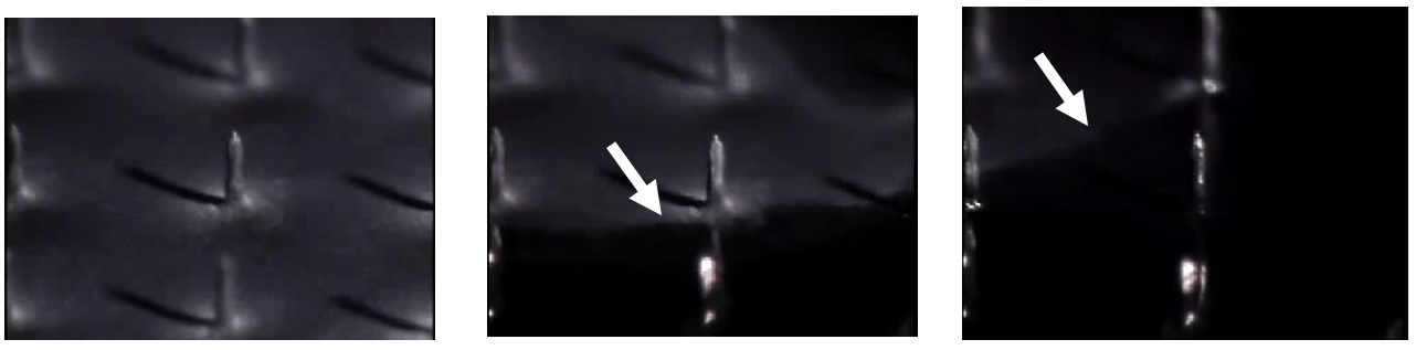
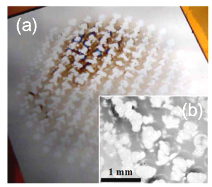
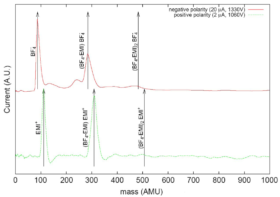
We have developed several planar arrays of externally-fed electrospray emitters. In all of them the emitting substrate is a monolithic array with as many as 1000 emitters coated with a nanoporous material (Fig. 2). The devices were originally intended for space applications and they used the ionic liquids EMI-BF4 and EMI-EM (Si/m-level electrical conductivity) as working fluids. However, the technology development is applicable to a wide range of applications Fig. 3 shows a cross-section and an exploded view of one of our most recent device developments, a gated planar ESI array with as many as 502 emitters and emitter densities of 4.5 emitters per mm2. In this device the emitters are arranged in rows (the apertures of the gate are slots). The emitters are micron-sharp pyramids coated with black silicon. We use black silicon to make the emitters wettable and transport the liquid to the emission sites (Fig. 4; click here to see a movie of the black silicon coating in action). The emitting substrate and the extractor are assembled using a DRIE-patterned springs, a high-voltage MEMS packaging technology that we pioneered and that we have developed for almost a decade. Fig. 5 shows the imprints of the arrays, evidencing uniform emission, and Fig 6 shows the TOF of the plume to demonstrate that in both polarities the spray is composed of solvated ions.